The anechoic chamber and semi-anechoic chamber are the shielded testing rooms with RF absorbers. They are designed to provide an optimal environment suitable for performing EMC testing. However, both chambers can be used in EMC testing; there are some differences between these two chambers. This article discusses the differences between the anechoic chamber and the semi-anechoic chamber.
See Also: Capacity Profile Of Phuc Gia Certification Inspection and Testing Center
1. Anechoic Chamber
1.1 What is an Anechoic chamber?
_638443725343091367.png)
Figure: (Fully) Anechoic Chamber
An anechoic chamber, derived from “an” (none) + “echoic” (echo), is a specialized room designed to eliminate echoes and reflections. Specifically, it prevents signals from being reflected back to the measurement sensors placed inside the chamber. These chambers are shielded rooms with walls, ceilings, and ground planes fully covered by radiation-absorbent material (RAM) or RF absorbers, earning them the name Fully Anechoic Chambers (FAC).
1.2. How Does It Work?
To prevent signal reflection, absorbers with specific shapes are installed on all reflective surfaces. These absorbers typically take the shape of pyramids (often referred to as cones) and are designed to either absorb the signal or scatter it in random directions away from the measurement sensor. The material and shape of these cones are optimized based on the type of signal (e.g., audio or electromagnetic) and its frequency characteristics.
The absorbers, made of lossy materials, convert incident electromagnetic energy into thermal energy, which dissipates into the surrounding air. This process effectively eliminates signal reflections within the chamber. Additionally, the chamber’s metallic shielding functions as a Faraday cage, blocking external interference and noise to create an environment free from disruptions.
1.3. Applications and Benefits
By eliminating signal reflections and external interference, anechoic chambers provide a free-field environment ideal for EMC (Electromagnetic Compatibility) testing. These chambers are essential for evaluating the performance of electrical and electronic devices across industries such as telecommunications, consumer electronics, aerospace, and defense. They are also widely used for measuring antenna gain, efficiency, and radiation patterns.

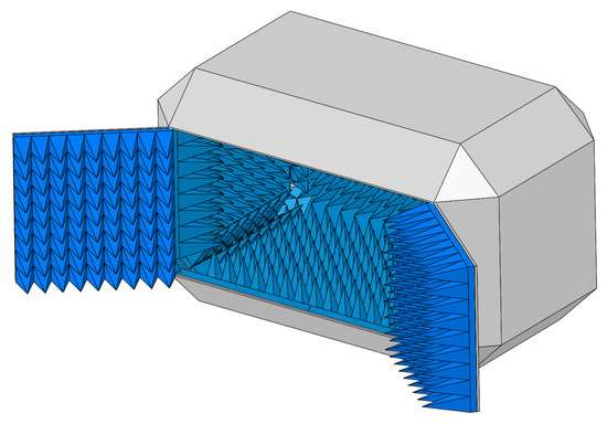
Figure: Anechoic chamber 3D design with doors for access to AUT.

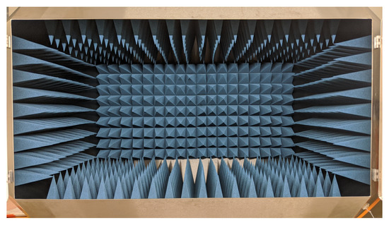
Figure: Realized anechoic chamber.
1.4. Why do we need an Anechoic Chamber?
An anechoic chamber is designed to ensure high accuracy and repeatability in measurements and testing.
When measuring a signal from a source (e.g., a transmitter) in a conventional chamber or open space with multiple reflective surfaces, the measured value may become inconsistent. This happens because the signal reaching the Device Under Test (DUT) is a combination of the original signal (line of sight) and numerous reflected versions. Such conditions lead to non-repeatable measurements (i.e., varying values across trials), and in some cases, the reflected signals may negatively interfere with the direct signal, resulting in an unstable connection.
In an anechoic chamber, RF-absorbing materials are used to convert electromagnetic wave energy into heat and dissipate it into the environment, completely eliminating wave reflections. The metallic shielding around the chamber acts as a Faraday cage, blocking external interference and ensuring a noise-free testing environment.
Anechoic chambers are widely used for EMC testing of electrical and electronic devices, including telecommunications equipment, consumer electronics, aerospace, and defense applications. Additionally, they are essential for measuring antenna gain, efficiency, and radiation patterns.
1.5. Types of Anechoic Chamber
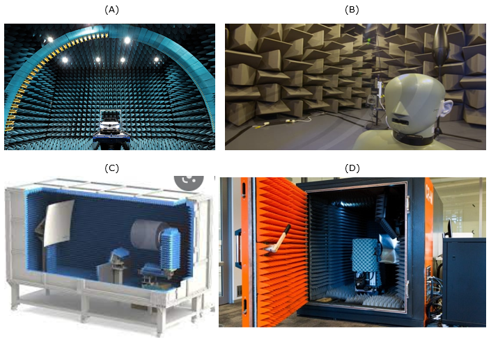
There are many different types and sizes of anechoic chambers. Some of the examples are shown below. There is a huge chamber like (A) so that you can put a whole vehicle there. Usually, chambers for audio testing (B) are pretty large because the wavelength of audio is pretty long (i.e., frequency is low). The Chambers like (C, D) are being used for testing mobile phones in RF/mmWave range that are relatively small comparing to (A), (B).

Figure: Types of Anechoic Chamber
1.2 What is a Semi-anechoic chamber (SAC)?
A semi-anechoic chamber (SAC) is a shielded room with walls and a ceiling covered with radiation-absorbent material (RAM) or RF absorbers; however, the ground plane is left as a flat reflective surface with NO absorber materials. The ground plane of the SAC is made of reflective material, usually a sheet metal ground plane. The metallic shielding of the chamber acts as a Faraday cage and prevents the entry of external interference or noises, offering an interference-free environment.
Since the ground floor is made as the reflective surface, this chamber partially absorbs the electromagnetic wave inside the chamber. Hence, the name semi-anechoic chamber. This chamber’s purpose is to simulate the real-world environment conditions (i.e., Open Area Test Site). The chamber creates a free-field environment above the ground plane. The semi-anechoic chamber (SAC) is particularly suitable for performing EMC testing of heavy vehicles or heavier items such as industrial machinery. The reflective solid floor area of the chamber is used as a work surface for supporting heavy items.
The objective of both the anechoic chamber and semi-anechoic chamber is to provide a controlled optimal environment for performing EMC testing. Both these chambers establish an accurate, stable, and repeatable testing environment for performing the EMC testing. The choice between the anechoic chamber and semi-anechoic chamber for EMC testing depends mainly on the tested products, testing requirements, and the EMC test standards adopted. Some EMC standards require testing in the anechoic chamber, and some standards require testing in the semi-anechoic chamber.
2. Key differences between Anechoic and Semi-anechoic Chambers
Here is an overview of the key differences between anechoic and semi-anechoic chambers in various aspects.
| Aspect | Anechoic chamber | Semi-anechoic chamber |
| Definition | It is a shielded room with walls, ceiling, and ground plane covered with radiation-absorbent material (RAM) or RF absorbers. |
It is a shielded room with walls and a ceiling covered with radiation-absorbent material (RAM) or RF absorbers. However, the floor area is a reflective surface with NO RF absorber materials. Here, the ground floor is made of reflective material, usually a sheet metal ground plane. |
| Absorptions of electromagnetic waves or sound energy. | Using RF absorbers, it completely absorbs electromagnetic waves or sound energy from all directions within the chamber and creates a reflections/echo-free, free-space environment. | Since the ground plane is made reflective surface, this chamber partially absorbs electromagnetic energy or sound energy. |
| Ground plane | Non-reflective | Reflective |
| Purpose | It simulates interference-free, free-space environment/conditions within the chamber. | It simulates interference-free, free-space environment/conditions above the ground plane. It simulates the real-world environment conditions (i.e., Open Area Test Site). |
| Uses | It is used to test the devices in a completely free-field environment, with No external interference. | It is used to test the devices in real-world scenarios, with No external interference. |
| Design and cost | The design of an anechoic chamber is complex and costly since all the surfaces are covered by absorbers. | Design is easy and lower cost as compared to the anechoic chamber. Since five surfaces are only covered by absorbers. |
| Equipment handling | Equipment handling is a little difficult as compared to a semi-anechoic chamber, because of ground floor is covered by RF absorbers. | Equipment handling is easy; because the ground floor does not have RF absorbers and acts as a work area for equipment under test (EUT). It is ideal for EMC testing of heavy vehicles or heavier items such as industrial machinery. |
| Used when | Used when the testing requires an environment with No reflections or echoes and No external interference. | Used when testing requires an environment with a reflecting ground plane and No external interference (for simulating real-world environments). |
See also:
- Phuc Gia Inspection Testing Center achieves ISO/IEC 17025:2017 accreditation – VILAS 1212:2019/BoA
- Phuc Gia Inspection & Testing Center achieves ISO/IEC 17025:2017 accreditation – VLAT 1.0388:2021/AOSC
- Phuc Gia Inspection Testing Center achieves ISO/IEC 17025:2017 accreditation – VALAS 09:2022/VACI
- Phuc Gia is authorized by MOST to certify products and goods in compliance with QCVN 9:2012 and QCVN 19:2019
For any further information please contact:
PHUC GIA CERTIFICATION CENTER
PHUC GIA INSPECTION & TESTING CENTER
PHUC GIA LABORATORY CORPORATION.
Address: ICD Long Bien, No. 01 Huynh Tan Phat, Sai Dong B Industrial Park, Thach Ban Ward, Long Bien District, Hanoi City, Vietnam.
Head office: Hoa Cuong Building, No. 18, Lane 11, Thai Ha, Trung Liet Ward, Dong Da District, Hanoi City, Vietnam.
Hotline: 0981 996 996/ 0982 996 696/ 024 7779 6696
Email: lab@phucgia.com.vn/ cert@phucgia.com.vn / info@phucgia.com.vn
Website: phucgia.com.vn
Working time: Monday to Friday 8:00 – 18:30; Saturday 8:00 – 12:00

_638443726766935961.png)