1. What is the IP Index in LED lamps? What is its significance?
IP (Ingress Protection) – This is a measure of the protection an item will have against solid objects (sand, dust, microscopic dust, etc.) and liquids.
According to the IP Index rating, it will consist of two numbers: The first number refers to the protection against solid objects (sand, dust, microscopic dust, etc.), and the second number refers to the protection against the ingress of liquids.
See more: Capacity Profile Of Phuc Gia Laboratory Corporation
What is the assessment of the waterproof IP Index in waterproof LED lamps?
Each IP Index rating has two defining numbers, both of which can provide you with complete information regarding the level of protection. A higher number means the LED lamp has better resistance against solid objects or liquids.
- The first number (0 – 6): Refers to the level of protection against solid objects and moving parts, such as dust particles, small debris, or various solid substances.
- The second number (0 – 9): Refers to the level of protection against liquids or moisture.
Please refer to the chart below to better understand the protection levels for each specific parameter:

2. Resistance to dust, solid objects, and moisture
2.1 General requirements
This section specifies requirements and tests for luminaires classified as resistant to dust, solid objects, and moisture, including ordinary luminaires.
2.2 Tests for ingress of dust, solid objects, and moisture
The enclosure of the luminaire shall provide a degree of protection against the ingress of dust, solid objects, and moisture in accordance with the classification of the luminaire and the IP Index marked on the luminaire.
Note 1: The tests for ingress of dust, solid objects, and moisture specified in this standard are not all identical to the tests in TCVN 4255 (IEC 60529) due to the technical characteristics of luminaires. An explanation of the IP Index system is provided in Annex A.
Explanation of the IP Index for protection levels
For a full detailed description, see TCVN 4255 (IEC 60529) from which the following is quoted. The types of protection covered by this classification system are as follows:
a) Protection of persons against contact with or approach to live parts and against contact with moving parts (other than smooth rotating shafts and the like) inside the enclosure, and protection of the equipment against the ingress of solid foreign objects.
b) Protection of the equipment inside the enclosure against harmful ingress of water.
The symbols indicating the degrees of protection consist of the characteristic letters IP followed by two digits (“characteristic digits”) indicating conformity with the conditions specified in Table A.1 and A.2, respectively. The first digit indicates the degree of protection described in point a) above, and the second digit indicates the degree of protection described in point b) above.
Table A.1 – Degrees of protection indicated by the first characteristic digit
| First characteristic digit | Grades of protection | |
| Brief description | Brief description of objects which shall not be able to enter the enclosure | |
| 0 | No protection | No special protection |
| 1 | Protected against the ingress of solid objects larger than 50 mm | A large surface of the body, such as a hand (but not protected against intentional contact). Solid objects with a diameter greater than 50 mm. |
| 2 | Protected against the ingress of solid objects larger than 12.5 mm | Fingers or similar objects with a length not exceeding 80 mm. Solid objects with a diameter greater than 12 mm. |
| 3 | Protected against the ingress of solid objects larger than 2.5 mm | Tools, wires, etc., with a diameter or thickness greater than 2.5 mm. Solid objects with a diameter greater than 2.5 mm. |
| 4 | Protected against the ingress of solid objects larger than 1.0 mm | Wires or strips with a thickness greater than 1.0 mm. Solid objects with a diameter greater than 1.0 mm. |
| 5 | Dust-protection | Does not completely prevent the ingress of dust, but the amount of dust ingress is only at a level where the equipment still operates satisfactorily. |
| 6 | Dust-tight | No ingress of dust |
Table A.2 – Degrees of protection indicated by the second characteristic digit
| Second characteristic digit | Grades of protection | |
| Brief description | Definition | |
| 0 | No protection | No special protection |
| 1 |
Protected against dripping water
|
Dripping water (vertically falling drops) shall have no harmful effect
|
| 2 |
Protected against vertically falling water drops when enclosure tilted up to 15°
|
Vertically falling drops shall have no harmful effect when the enclosure is tilted at any angle up to 15° on either side of the vertical
|
| 3 |
Protected against spraying water
|
Water falling as a spray at any angle up to 60° on either side of the vertical shall have no harmful effect
|
| 4 |
Protected against splashing water
|
Water splashed against the enclosure from any direction shall have no harmful effect
|
| 5 |
Protected against water jets
|
Water projected in jets against the enclosure from any direction shall have no harmful effect
|
| 6 |
Protected against powerful water jets
|
Water projected in powerful jets against the enclosure from any direction shall have no harmful effect
|
| 7 |
Protected against the effects of temporary immersion in water
|
Water shall not enter the enclosure in harmful quantities when the enclosure is temporarily immersed in water under standardized conditions of pressure and time
|
| 8 |
Protected against the effects of continuous submersion in water
|
The equipment is suitable for continuous submersion in water under conditions specified by the manufacturer
Note: Normally, this means that the equipment is hermetically sealed. However, with certain types of equipment, it can mean that water can enter but only in a manner that produces no harmful effects. |
| Special cleaning techniques are not covered by the IP Index. It is recommended that the manufacturer provide appropriate information regarding cleaning techniques if necessary. This information accompanies the recommendations contained in TCVN 4255 (IEC 60529) regarding special cleaning techniques. | ||
Compliance is checked by the appropriate tests specified in the clauses of the Test section from B.0 to B.9 and, for other IP parameters, compliance is checked by the tests specified in TCVN 4255 (IEC 60529).
Before the tests for the second characteristic digit, except for IP8, the luminaire with complete lamp(s) shall be switched on and brought to a stable operating temperature at the rated voltage.
The water used for these tests shall have a temperature of 15 °C ± 10 °C.
Luminaires shall be installed and wired as in normal use and placed in the most unfavorable position, with translucent glass covers (if any) fully fitted for the tests in sections B.0 to B.9 (in Annex B).
In cases where connection is made by a plug or similar device, this device shall be considered part of the complete luminaire and shall be included in the tests, and the same applies to all separate controlgears.
For tests in clauses B.3 to B.9, fixed luminaires designed so that, when installed, their body is in contact with the surface, shall be tested with a gasket of expanded metal mesh placed between the luminaire and the mounting surface. This gasket shall be at least as large as the projected external dimensions of the luminaire, and have the following dimensions:
| Mesh length | 10 mm to 20 mm |
|
Mesh width (Short way)
|
4 mm to 7 mm |
| Strand width | 1.5 mm to 2 mm |
|
Strand thickness
|
0.3 mm to 0.5 mm |
|
Overall thickness
|
1.8 mm to 3 mm |
Luminaires provided with drain holes shall be installed with the lowest drain hole open, unless otherwise specified in the manufacturer’s installation instructions.
If the installation instructions indicate that a drip-proof luminaire is intended for mounting on a ceiling or under a canopy, the luminaire shall be attached to the underside of a board or flat plate extending 10 mm beyond the perimeter of the luminaire part in contact with the mounting surface.
For recessed luminaires, parts in the cavity and parts projecting from the cavity shall be tested according to their IP classification as indicated in the manufacturer’s installation instructions. An enclosure for the part inside the cavity may be necessary for tests in clauses B.4 to B.9 (in Annex B).
B.0 Tests
Luminaires resistant to the ingress of solid objects (first characteristic IP digit is 2) shall be tested with the standard test probe specified in TCVN 4255 (IEC 60529) according to the requirements of this standard.
Note: Tests for luminaires with the second characteristic IP digit using a ball as specified in TCVN 4255 (IEC 60529) are not required.
Luminaires resistant to the ingress of solid objects (first characteristic IP digits 3 and 4) shall be tested at all possible points (except gaskets) with a probe corresponding to test probe C or D of IEC 61032, applied with the force indicated in Table B.
Table B: Testing of luminaires against the ingress of solid objects
| Test probe according to IEC 61032 |
Test wire diameter mm |
Applied force N |
|
| First characteristic IP Index digit: 3 | C | + 0,05 2,5 – 0,00 |
3 ± 10% |
| First characteristic IP Index digit: 4 | D | + 0,05 1 – 0,00 |
1 ± 10% |
The tip of the probe wire shall be cut perpendicular to its length and be free from burrs.
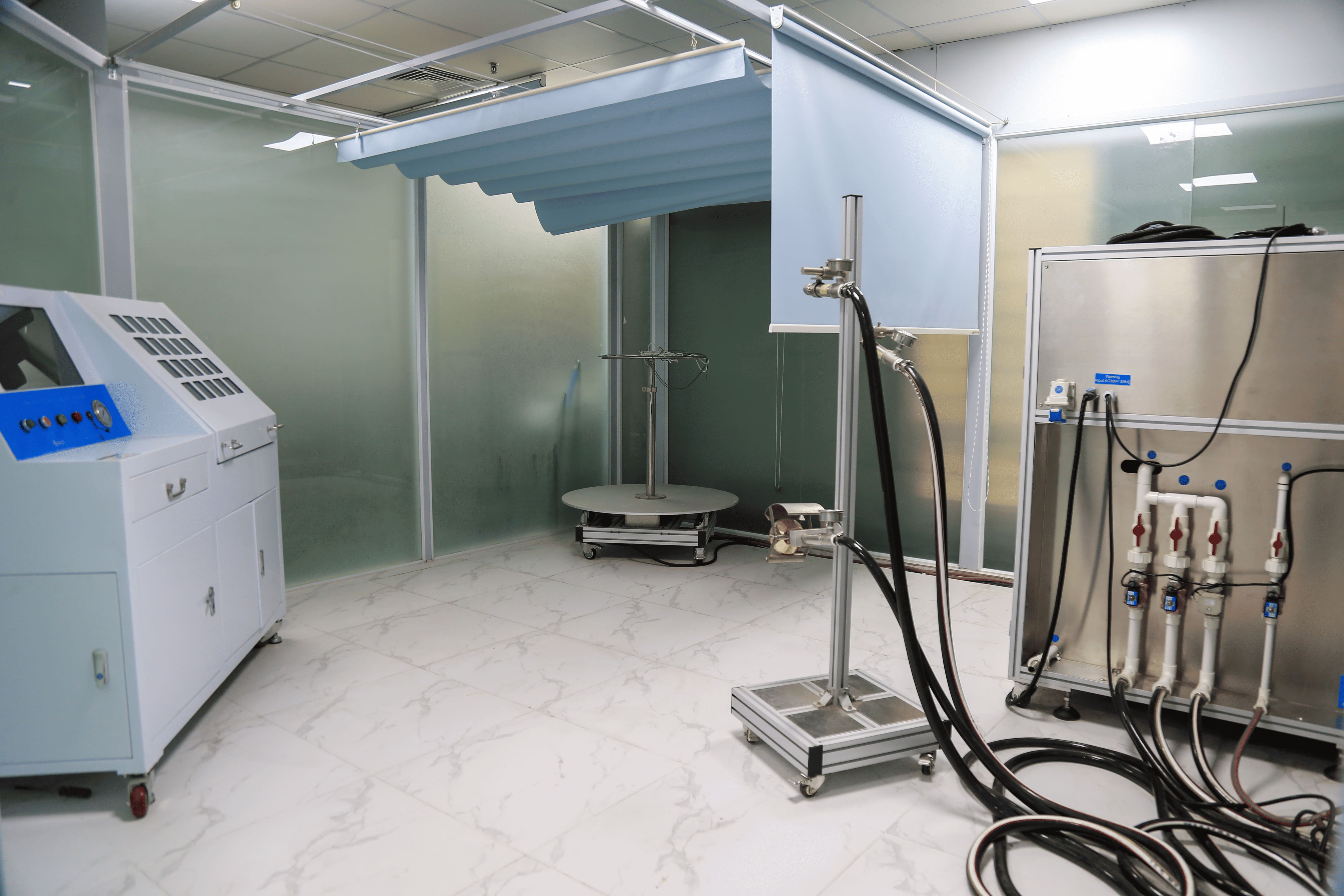
B.1 Dust-proof luminaires (first characteristic IP Index digit 5) shall be tested in a dust chamber similar to that shown, in which talcum powder is maintained in suspension by an air current. This chamber must contain 2 kg of talcum powder per cubic meter of its volume. The talcum powder used must be able to pass through a square-mesh sieve with a nominal wire diameter of 50 µm and a nominal free distance between wires of 75 µm. This sieve must not be used for more than 20 tests.
The test shall be conducted as follows:
a) The luminaire is suspended outside the dust chamber and operated at the rated supply voltage until it reaches operating temperature. b) The luminaire, while still operating, is placed in the position of least disturbance in the dust chamber. c) The door of the dust chamber is closed. d) The fan/blower is switched on so that the talcum powder is maintained in suspension. e) After 1 min, switch off the power to the luminaire and allow it to cool for 3 h while the talcum powder remains in suspension.
Note: The 1 min interval between switching on the fan/blower and switching off the luminaire ensures that the talcum powder is actually in suspension around the luminaire during the initial cooling process, which is very important for smaller luminaires. Initially, operating the luminaire as in point a) is to ensure the test chamber does not overheat.
B.2 Dust-tight luminaires (first characteristic IP Index digit 6) are tested according to the dust-proof luminaire procedure.
B.3 Drip-proof luminaires
B.3.1 Drip-proof luminaires (second characteristic IP Index digit 1) shall be subjected to artificial rain at 1 mm/min for 10 min, falling vertically from a height of 200 mm onto the highest part of the luminaire.
B.3.2 Drip-proof luminaires (second characteristic IP Index digit 2) shall be subjected to artificial rain at 3 mm/min for 10 min, falling vertically from a height of 200 mm onto the highest part of the luminaire, when the luminaire is placed in the most unfavorable position and tilted at any angle up to 15° on either side of the vertical axis.
B.4 Rain-proof luminaires (second characteristic IP Index digit 3) are subjected to a water spray for 10 min using a spraying device. The radius of the semi-circular tube shall be as small as possible and appropriate to the size and position of the luminaire.
The tube shall be drilled so that the water jets are directed toward the center of the circle and the water flow rate at the inlet of the spraying device shall be approximately 0.07 l/min ± 5 % per hole multiplied by the number of holes (approximately 80 kN/m2).
The tube shall oscillate through an angle of 120°, 60° on each side of the vertical axis, the time for one complete oscillation (2 x 120°) being about 4 s.
The luminaire shall be mounted on the centerline of the tube so that the ends of the luminaire receive full coverage of the sprayed water jets. The luminaire shall be rotated around its vertical axis during the test at a speed of 1 r/min.
After this 10 min period, switch off the power to the luminaire and allow it to cool naturally while continuing the water spray for another 10 min.
Note: In Japan, the oscillating tube test and the spray nozzle test as described in TCVN 4255 (IEC 60529) are accepted.
B.5 Splash-proof luminaires (second characteristic IP Index digit 4) are sprayed with water from all directions for 10 min using the spraying device described in B.4. The luminaire shall be mounted below the centerline of the tube so that the ends of the luminaire are sufficiently covered by the water jets.
The tube shall oscillate through an angle of approximately 360°, 180° on either side of the vertical axis, the time for one complete oscillation (2 x 360°) being about 12 s. The luminaire shall be rotated around its vertical axis during the test at a speed of 1 r/min.
The support for the device under test shall be in the form of a grid to avoid acting as a baffle. After this 10 min period, switch off the power to the luminaire and allow it to cool naturally while continuing the water spray for another 10 min.
Note: In Japan, the oscillating tube test and the spray nozzle test as described in TCVN 4255 (IEC 60529) are accepted.
B.6 Jet-proof luminaires (second characteristic IP Index digit 5) are switched off and immediately after, subjected to a water jet for 15 min from all directions using a hose with a nozzle. The nozzle shall be held 3 m from the sample.
The water pressure at the nozzle shall be adjusted to achieve a water flow rate of 12.5 l/min ± 5 % (approximately 30 kN/m2).
B.7 Powerful jet-proof luminaires (second characteristic IP Index digit 6) are switched off and immediately after, subjected to a water jet for 3 min from all directions using a hose with a nozzle. The nozzle shall be held 3 m from the sample.
The water pressure at the nozzle shall be adjusted to achieve a water flow rate of 100 l/min ± 5 % (approximately 100 kN/m2).
B.8 Watertight luminaires (second characteristic IP Index digit 7) are switched off and immediately after, immersed in water for 30 min so that the highest point of the luminaire is at least 150 mm below the water surface and the lowest part of the luminaire is subjected to a minimum water column height of 1 m. The luminaire shall be held in position by its normal fixing means. Luminaires using tubular fluorescent lamps shall be placed in a horizontal position, 1 m below the water surface, with the diffuser facing upwards.
Note: This treatment is not severe enough for luminaires working underwater.
B.9 Pressure-watertight luminaires (second characteristic IP Index digit 8) are heated by switching on the lamp or by another suitable method, so that the temperature of the luminaire enclosure is 5 °C to 10 °C higher than the temperature of the water in the test tank.
Thereafter, the luminaire shall be switched off and subjected to a water pressure equal to 1.3 times the pressure corresponding to the rated maximum immersion depth for a duration of 30 min.
For IP2X luminaires, the enclosure means the part of the luminaire containing the main parts other than the lamp and the optical control gear.
Note 2: Since luminaires have no dangerous moving parts, the safety level specified in TCVN 4255 (IEC 60529) is achieved.
Portable luminaires, wired as in normal use, shall be placed in the most unfavorable position for normal use.
Glands, if any, shall be tightened with a torque equal to two-thirds of the torque applied to the gland in Test C.
Threaded seals shall be fitted with a cylindrical metal rod with a diameter equal to the nearest lower integer in millimeters compared to the internal diameter of the seal to be sealed. This seal shall be tightened with a suitable wrench, with the torque indicated in Table C.1 applied to the wrench for 1 min.
Table C.1 – Torque test on glands
|
Test rod diameter (mm) |
Torque |
|
| Metal gland (Nm) | Molded plastic gland (Nm) | |
| Up to 7 | 6,25 | 2,5 |
| Over 7 to 14 | 6,25 | 3,25 |
| Over 14 to 20 | 7,50 | 5 |
| Over 20 | 10 | 7,50 |
After the test, the luminaire and seals shall show no signs of damage.
Screws fixing covers, other than hand-operated fixing screws for glass covers, shall be tightened with a torque equal to two-thirds of the torque specified in Table D.
Screw-type covers shall be tightened with a torque whose value in Newton-meters shall numerically equal one-tenth of the nominal diameter of the screw thread in millimeters. Screws fixing other covers shall be tightened with a torque equal to two-thirds of the torque specified in Table D.
Table D – Torque for testing screws
|
Nominal major diameter of screw thread (mm) |
Torque (Nm) |
||
| 1 | 2 | 3 | |
| Up to and including 2.8 | 0.20 | 0.40 | 0.4 |
| Over 2.8 up to and including 3.0 | 0.25 | 0.50 | 0.5 |
| Over 3,0 up to and including 3,2 | 0.30 | 0.60 | 0.5 |
| Over 3,2 up to and including 3,6 | 0.40 | 0.80 | 0.6 |
| Over 3,6 up to and including 4,1 | 0.70 | 1.20 | 0.6 |
| Over 4,1 up to and including 4,7 | 0.80 | 1.80 | 0.9 |
| Over 4,7 up to and including 5,3 | 0.80 | 2.00 | 1.0 |
| Over 5,3 up to and including 6,0 | – | 2.50 | 1.25 |
| Over 6,0 up to and including 8,0 | – | 8.00 | 4.00 |
| Over 8,0 up to and including 10,0 | – | 17.00 | 8.50 |
| Over 10,0 up to and including 12,0 | – | 29.00 | 14.50 |
| Over 12,0 up to and including 14,0 | – | 48.00 | 24.00 |
| Over 14,0 up to and including 16,0 | – | 114.00 | 57.00 |
After completion of the tests, the luminaire shall be subjected to the specified electric strength test and inspection shall show:
a) No deposit of talcum powder in dust-proof luminaires, as if this powder were conductive, the insulation would not comply with the requirements of this standard. b) No deposit of talcum powder inside the enclosure for dust-tight luminaires; c) No water traces on electrical connections, current-carrying parts, or on insulation that could become dangerous to the user or the surrounding environment, for example, in cases where creepage distances and air clearances could be reduced below the specified values; except only for SELV conductors where the load voltage does not exceed 12 V RMS or 30 V ripple-free DC and on conductors protected against corrosion.
Note 3: Some aspects of corrosion protection are specified.
For luminaires without drain holes, no water shall have entered.
Note 4: Care should be taken not to confuse condensation with water entry.
For luminaires with drain holes, water entry including condensation during the test is permitted if the hole can drain effectively and provided the water does not reduce creepage distances and air clearances below the minimum levels specified in this standard;
d) No water traces entered into any part of watertight or pressure-watertight luminaires; e) No contact with live parts by the relevant test probe for the first characteristic IP Index digit 2; f) No entry into the luminaire enclosure by the relevant test probe for the first characteristic IP Index digits 3 and 4; g) For luminaires with appropriate drain holes and luminaires with ventilation slots for forced cooling, no contact with live parts through the drain holes and ventilation slots by the relevant test probe for the first characteristic IP Index digits 3 and 4; h) No water traces on any part of the lamp requiring protection from splashing water as indicated in the “information for luminaire design” section of the relevant lamp standard; i) No damage, for example, breaking or cracking of the protective shield or glass enclosure that adversely affects safety or protection against the ingress of moisture.
2.3 Humidity test
All luminaires shall withstand humidity conditions that may occur in normal use.
Compliance is checked by humidity treatment, immediately following the tests.
Cable entries, if any, shall be left open; if there are knock-outs, one of the knock-outs shall be knocked out.
Parts that can be removed by hand, for example, electrical accessories, enclosures, protective glass, etc., shall be removed and, if necessary, subjected to humidity treatment together with the main part.
The luminaire is placed in the most unfavorable position in normal use, in a humidity cabinet containing air with a relative humidity maintained at 91 % to 95 %. The temperature of the air everywhere where samples are placed shall be maintained within 1 °C of any appropriate value “t” from 20 °C to 30 °C.
Before being placed in the humidity cabinet, the sample shall be brought to a temperature between “t” and (t + 4) °C. The sample shall be kept in the cabinet for 48 h.
Note: In most cases, the sample can be brought to the specified temperature between “t” and (t + 4) °C by keeping it in a room at this temperature for at least 4 h before the humidity treatment.
To achieve the specified conditions in the cabinet, it is necessary to ensure constant air circulation inside the cabinet and a thermally insulated cabinet is usually used.
After this treatment, the sample shall not be damaged in a way that affects compliance with the requirements in this standard.
For more details, please contact us at:
PHUC GIA LABORATORY CORPORATION
PHUC GIA CERTIFICATION CENTER
PHUC GIA INSPECTION TESTING CENTER
Address: ICD Long Bien, No. 01 Huynh Tan Phat, Sai Dong B Industrial Park, Long Bien Ward, Hanoi City, Vietnam.
Hotline: 0981 996 996/ 0982 996 696/ 024 7779 6696
E-mail: lab@phucgia.com.vn/cert@phucgia.com.vn/info@phucgia.com.vn
Website: phucgia.com.vn
Working time: Monday to Friday 8:00 – 18:30; Saturday 8:00 – 12:00

![QUOTATION – Testing and Other Certification Services [2026]](https://phucgia.com.vn/wp-content/uploads/2017/03/bao-gia-thu-nghiem-chung-nhan.png)